Hardware
The hardware design was completed to meet and expand upon the vehicle's current data-acquisition system. The design includes a custom printed circuit board (PCB) with solely surface-mount components, which significantly reduces the size of the PCB in comparison to through-hole components.
The board features two microcontrollers and through-hole breakout mounting to accommodate permanent system sensors and rapid prototyping.
The selection of components was carefully completed to ensure required functionality was achieved. High-resolution analog-to-digital converters (ADCs) were selected for the sensor inputs [1]. Voltage regulators were used to ensure stable reference voltages, improving the accuracy of the ADC conversions [2]. Amplification and 16-bit ADCs were added to accommodate strain peripherals [3, 4].
User interaction with the board was kept in mind during the design. The connectors were selected such that the user can easily add and remove sensors during testing and development. JTAG and ISP headers were included to expedite the firmware development process. A duplicate design was included so that long-term sensors and firmware could exist independently from short-term projects.


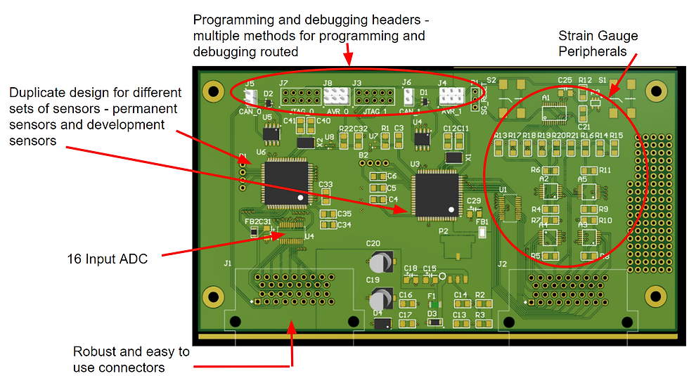
Figure 1: CANDAQ PCB images
[1] Texas Instruments, “Choose the right A/D converter for your application”, Application Note. Available: https://www.ti.com/europe/downloads/Choose the right data converter for your application.pdf
[2] Texas Instruments, M. Oljaca, B. Baker, “How the voltage reference affects ADC performance, Part 2”, 2009. Available: http://www.ti.com/lit/an/slyt339/slyt339.pdf.
[3] Texas Instruments, “ADS833x Low-Power, 16-Bit, 500-kSPS, 4- and 8-Channel Unipolar Input Analog-to-Digital Converters With Serial Interface”, ADS8332IBPWR Datasheet, Aug. 2016.
[4] Burr-Brown Products from Texas Instruments, “Low-Power, Single-Supply, CMOS INSTRUMENTATION AMPLIFIERS”, INA2332AIPWR Datasheet, Oct. 2006.